August 29, 2025: Featured in Random Wire issue 146 is the construction of a small digital hotspot with a Raspberry Pi Zero 2WH and an MMDVM hat. Build a hotspot for less than $100.
Featured: build a miniature hotspot for M17

This may be one of the simplest hotspot builds ever: a Raspberry Pi Zero 2WH, an MMDVM hat, and a case. For less than $100, you can build a working hotspot that works with D-STAR, YSF, M17, DMR, P25, NXDN, and POCSAG.
I am dedicating this hotspot for use with my M17 radios, but it will work with many digital modes. To operate the hotspot, I’m using WPSD even though WPSD no longer supports M17. The M17 Project folks forked WPSD at a slightly older version that does include M17 support, so that’s what I’ll use for this dedicated-to-M17 hotspot.
Parts list
$28.90: UeeKKoo Pi Zero 2 W Basic Kit with Color-Coded Pre Soldered Header RPi Zero 2 W + Pi Zero 2W Case + Mini HDMI to HDMI Adapter + Micro USB+OTG Cable +Screwdriver (5 Items) (this is an affiliate link)
$9.95: CanaKit 5V 2.5A Raspberry Pi 3 B+ Power Supply/Adapter (UL Listed) (this is an affiliate link)
$21.99: C4Labs – JRZ-1S case for Raspberry Pi Zero/Zero W & JumboSPOT or Lonestar MMDVM Simplex (this is an affiliate link)
$34.70: AURSINC MMDVM Hotspot Board (V1.5.2) + Antenna Support UHF VHF Support P25 DMR YSF DSTAR NXDN POCSAG for Raspberry Pi-Zero W, 2W, Pi 3, 3B, 3B+, 4 (with OLED) (this is an affiliate link)
$7.99 (optional): Geekworm Heatsink CPU Cooler for Raspberry Pi, 8PCS Copper Heatsinks with Thermal Conductive Adhesive Compatible with Raspberry Pi/Orange Pi/Rock Pi/Tinker Board/PCB Board CPU Chip (this is an affiliate link)
$12.99 (optional): Smays Ethernet Adapter for onn Android TV 4K Streaming Device Box – Micro USB OTG Hub (this is an affiliate link)
$13.96 (optional):PoE Splitter 5V2.5A Output DC Plug Compatible 5.5×2.5mm & 5.5×2.1mm, IEEE802.3af Standard Compliant PoE Power Adapter for Security IP Camera/Voip Phone/AP, PTD-AF-5V(this is an affiliate link)$10.89 (optional): UCTRONICS IEEE 802.3af Micro USB Active PoE Splitter Power Over Ethernet 48V to 5V 2.4A for Tablets, Dropcam or Raspberry Pi 2/3B+ (48V to 5V 2.4A) (this is an affiliate link)
Or $14.49 (optional): 2.5G Micro USB PoE Splitter 5V/3A, PoE to Micro USB 5V/3A 15W Output, 2.5Gbps Ethernet Comply IEEE802.3af/at, Plug and Play for Smart Home (this is an affiliate link)
The $13.96 PoE splitter is crossed out because that is not the model I needed. I mistakenly ordered it and discovered it was wrong during the organization of parts for the project. The PoE splitter I meant to buy carries power over a microUSB plug. To cover for ordering the wrong one, I immediately ordered one each of the following PoE splitters. The $10.89 splitter is rated to 2.4 amps, which is slightly below the minimum recommended amperage for the Raspberry Pi 2 of 2.5 amps. Maybe it will work. The MMDVM hat and small display represent unusual power draws, so I also ordered the $14.49 splitter that is rated to 3 amps. I’ll let you know how these two splitters work powering the hotspot.
Hint: the cheaper PoE splitters tend to be lower amperage devices. Increased amperage capacity means about a 50% price increase, in general. It’s cheaper to use the CanaKit 5V/2.5A power supply, but for this build, I’m also trying to demonstrate the ability to safely use a Power-over-Ethernet switch to power the hotspot using only an Ethernet cable.
Not including the PoE splitter shenanigans, what is the actual cost of this working hotspot?
$28.90 for the Raspberry Pi Zero 2WH
$9.95 for the power supply
$21.99 for the nice case
$34.70 for the MMDVM hat
Total cost: $95.54. The copper heatsinks are optional. That’s right: for less than $100, you can build a working hotspot that can handle D-STAR, YSF, M17, DMR, P25, NXDN, and POCSAG.
Why these parts?
I’ve used the UeeKKoo Raspberry Pi Zero 2 board before. The advantage of this particular board is the GPIO header is already soldered in. That’s worth a few extra bucks to me. (If all you need is the RPi Zero 2 WH, this choice will save you $2.) If you’re handy with a soldering iron and have some time to fiddle, you can save a little bit of money by purchasing an RPi with an unsoldered, loose GPIO header. Note that you can save a few more bucks by buying a used RPi (yes, Amazon often makes these available).
As stated in previous Random Wire newsletters, I like the official Raspberry Pi power supply and the one by CanaKit. For this assembly, I chose the CanaKit PS even though I may not need it (explanation coming in a few paragraphs).
I do like seeing into the device so the clear acrylic C4Labs case meets that desire. Also, C4Labs is based in Portland, Oregon, where I spend a lot of time. The screws that bind the layers together are stainless steel and rubber feet are included. (C4Labs also makes some gaming things, so if you are into tabletop role playing or dice towers, check them out.)
I’ve used a couple of AURSINC MMDVM boards in the past, and they’ve generally performed well. (My nice home-built duplex hotspot uses an AURSINC board.) I defaulted to AURSINC because they are ubiquitous and affordable. If it doesn’t work right, I can always upgrade to a different board.
The Geekworm copper heatsinks are more expensive than others, and that’s because they are solid copper. They might perform slightly better than aluminum (copper has better thermal conductivity than aluminum) but there are arguments on both sides of this question. You can feel the heavier weight of the copper heatsinks in your hand, compared to aluminum heatsinks. Since I’m using a clear case, the heatsinks will be visible. I think the copper heatsinks add a bit of visual interest to the hotspot.
Sometimes I hook up a mouse and keyboard directly to a Raspberry Pi but those peripherals use USB-A ports, which the RPi doesn’t have. A USB hub addresses this. I’ve used the Smays brand adapter before so I know it works. The other benefit of the adapter is the Ethernet port in it, allowing me to easily connect the hotspot directly to my network switch.
And speaking of my switch, I’m using a Power-over-Ethernet (PoE, pronounced pee-oh-ee) switch. The PoE splitter I ordered will allow me to power the hotspot directly from an Ethernet cable connected to that switch. Since the Raspberry Pi Zero 2 isn’t PoE capable, the PoE splitter sends power to the microUSB connector (which will plug into the RPi) and sends data to an Ethernet port (which I’ll connect to the Smays adapter mentioned above). Doing this means I don’t need to use the CanaKit adapter. I’m guessing most subscribers aren’t using a PoE switch so the CanaKit adapter is the recommended solution.
I think the PoE splitter provides a bit of peace of mind, too. While it is generally safe to connect a Raspberry Pi single-board computer to an IEEE 802.3-compliant PoE switch, I don’t think that’s a guarantee. I have a much older desktop PC that might precede the 802.3 standard, and when I connected it to a PoE switch, it damaged the Ethernet port on the computer. My takeaway from this is if you are going to use a PoE switch to connect devices and you don’t know if it is safe to do so, use a splitter to separate the power from the Ethernet data lines. You don’t have to plug the power plug on the splitter into anything. When I do this, I use a small piece of electrician’s tape to cover the loose power plug that hangs off the splitter.
Parts received
Here are the parts received for this build, before I separated all the bits and pieces to begin assembling the hotspot.
Software is a WPSD fork
M17 support was dropped from WPSD because M17 was removed from the upstream codebase. (Want more? Start at https://rz01.org/wpsd-m17/ and be sure to hit the link to the Zero Retries article linked in that post.) Some good folks rolled back the clock a little bit and forked the last version of WPSD that supported M17. That’s the branch I’m using for this M17-focused hotspot. It is called the WPSD M17 Community Fork.
How to download and install the WPSD M17 Community Fork is covered in sufficient detail on the Community Fork page.
Since I’m configuring the hotspot for just M17 use, I don’t need to bother with the Brandmeister API key in the advanced settings. (Of course, if I’m ever going to use it for DMR or Yaesu System Fusion, I’ll need to make sure the settings for those modes are correct.)
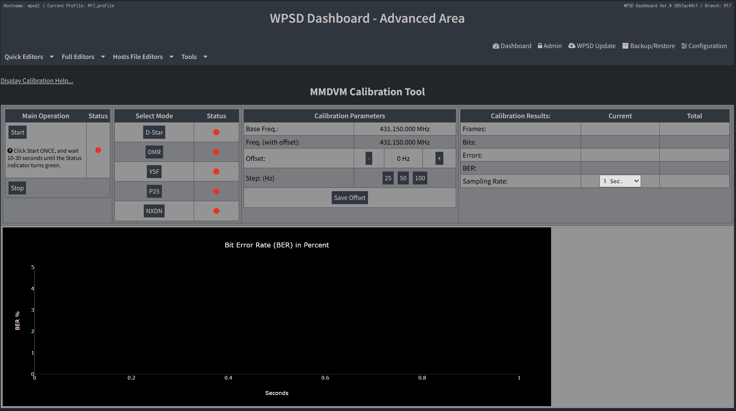
Calibration? Yes
Should the MMDVM hat be calibrated? I believe so, especially as this is a new build. The procedure is relatively simple in WPSD. In the WPSD dashboard: Admin —> Advanced —> Tools —> MMDVMHost Calibration.
And I discovered that M17 calibration is not listed! I calibrated using my YSF (Yaesu System Fusion) radio, and ultimately, no offsets were required.
Does it work? Yes!
Here are a couple of videos and an audio recording to demonstrate startup, shutdown, and connecting to an M17 reflector. (Apologies for sometimes referring to the hotspot as a node. Habit.)
Here’s the first startup video I did as the sun rose over the Lake House.
I did another startup and shutdown video a few minutes later:
And here is audio of the hotspot connecting to a few different M17 reflectors.
And it works on the PoE splitter
A Power-over-Ethernet splitter with a microUSB connector arrived this week. This is the 5 volt, 2.4 amp version. If you recall, the recommended power supply is 2.5 amps for the Raspberry Pi Zero 2 board family. On top of that (literally), there is the MMDVM hat with a display (albeit a small one). I wasn’t sure if a 2.4A PoE splitter would supply sufficient power, but it appears it does. That’s good to know as the 2.4A splitters cost a few dollars less than the 3A splitters.
However, I found that the 2.4A splitter gets warmer than the 3.0A splitter. I’m keeping the 3A splitter in service for this node.
The connected pieces look like this:
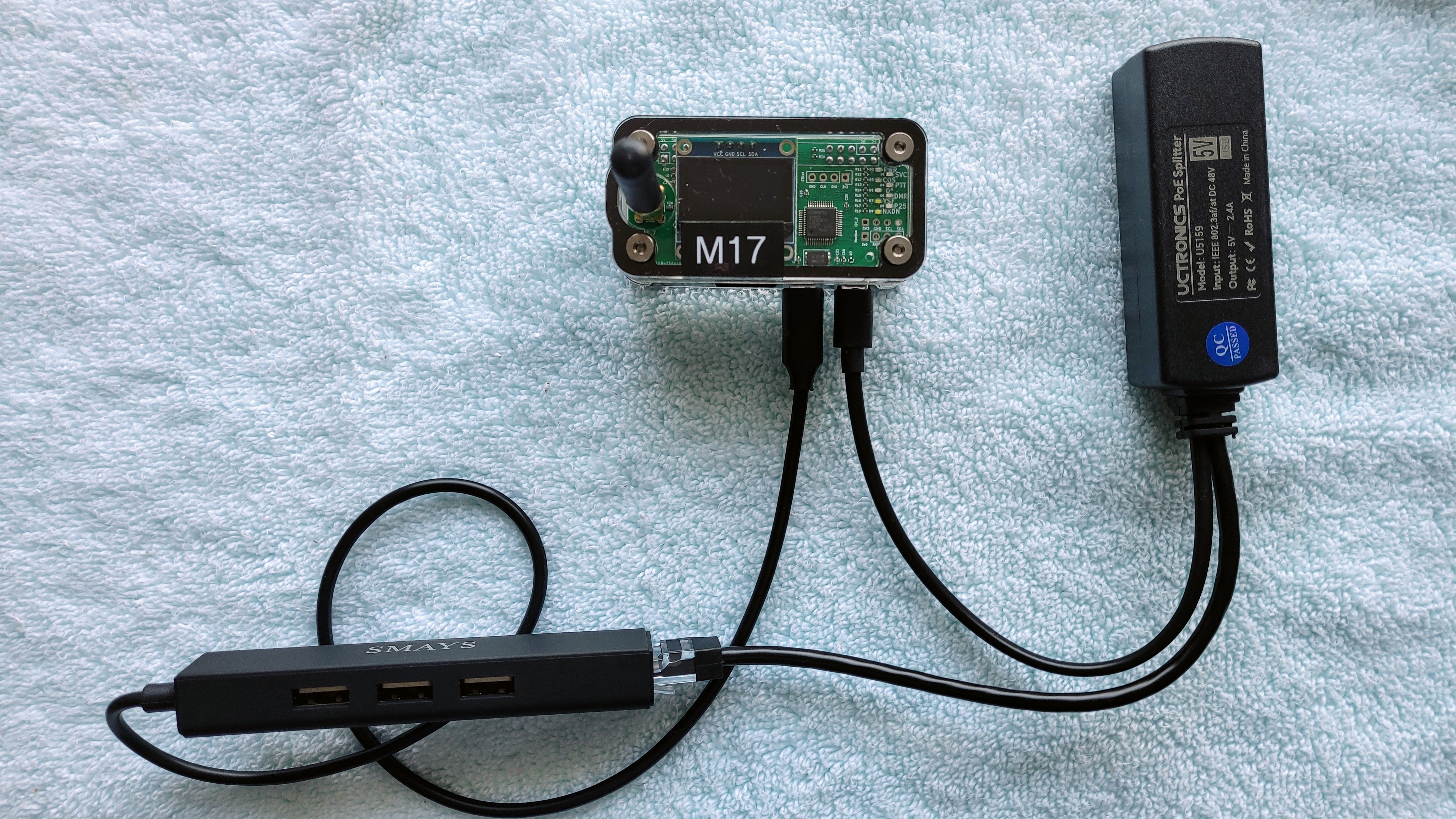
The hotspot is top center in the picture, the splitter is top right, and the USB hub is bottom left. On the Raspberry Pi Zero 2 board, there are two microUSB ports. The one farthest to the right in this view is the power port. The one next to it is for networking and peripherals.
I ran a long Ethernet cable from my PoE switch to another part of the room, then plugged the cable into the PoE splitter. The microUSB plug on the splitter goes into the power port on the hotspot. The Ethernet plug on the splitter goes into a USB hub that also has an Ethernet port, and that hub is plugged into the other microUSB port on the hotspot. It’s easier to see this in the photo above than to describe it in words.
As you can see in the photos below, the hotspot booted up just fine in this configuration.
Why would you do such a thing? For one, you may not have an outlet near where you want to place your hotspot. That is my situation at the lake house which has relatively few power outlets. Using the PoE switch and attaching a PoE splitter to the hotspot means I can provide networking and power using only an Ethernet cable. That makes it much easier for me to place the hotspot in an out-of-the-way place, without worrying about finding a nearby power outlet.
The other reason is when you have several machines and each one takes a wall wart power adapter, those adapters take up a lot of space. My PoE switch is quite compact.
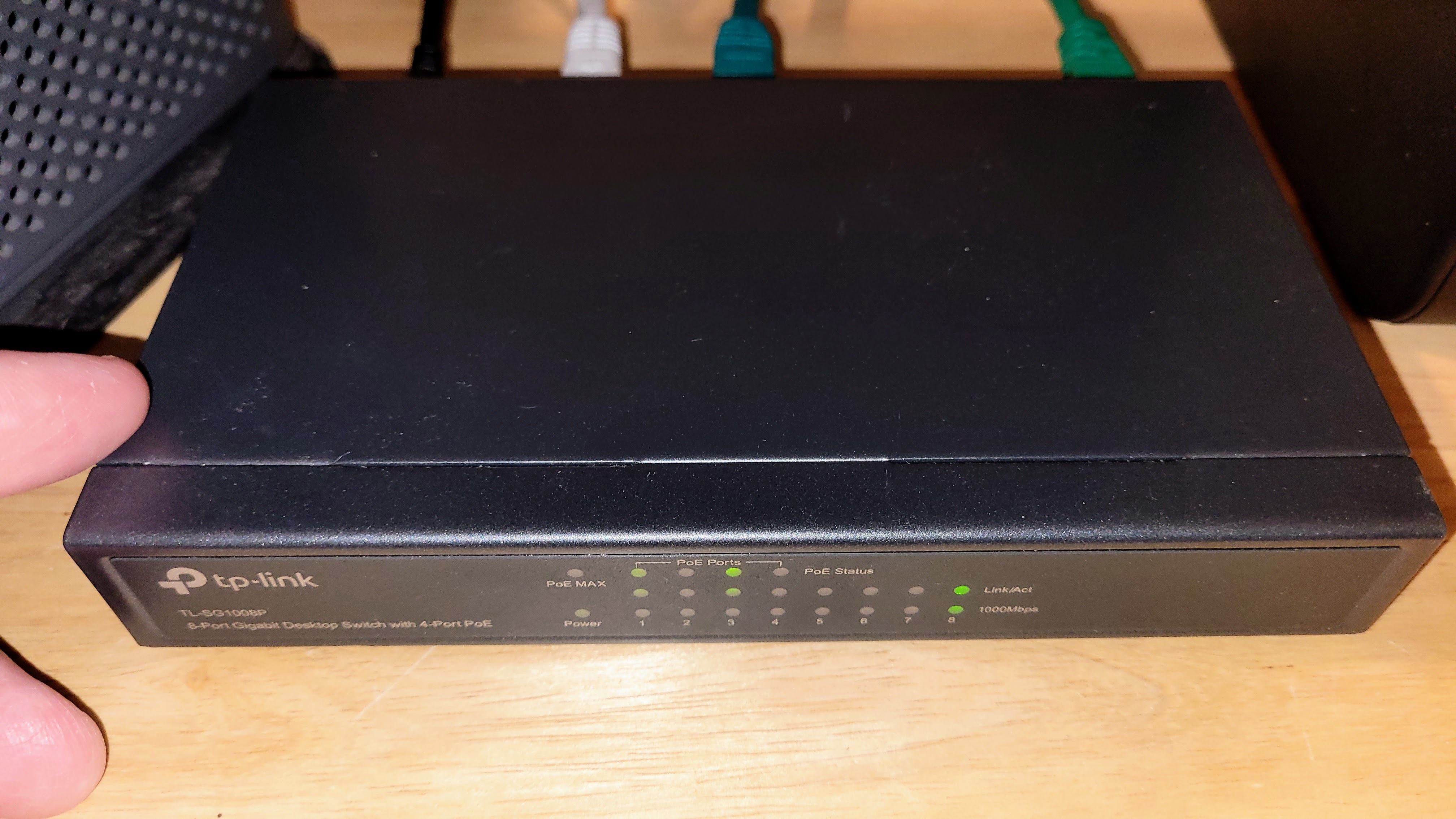
I bought the switch in December 2020 and it’s been in continuous service since then.
TP-Link 8 Port Gigabit Ethernet Network Switch – Ethernet Splitter | Plug & Play | Fanless | Sturdy Metal w/ Shielded Ports | Traffic Optimization | Unmanaged | Lifetime Protection (TL-SG108) (this is an affiliate link)
For just $18, this switch has been one of my better purchases.

Adding DTMF commands to AllStarLink 3
Dual tone multi-frequency (DTMF) is the sounds or tones generated by a telephone when the numbers are pressed. These tones are transmitted with the voice channel. DTMF is used to control automated equipment and signal user intent, such as the number they wish to dial. Each key has two tones at specific frequencies.
To send DTMF tones with a SIP phone, you dial the asterisk symbol and a series of numbers for a DTMF command. On most handheld radios, you hold down the push-to-talk (PTT) button while you press the asterisk symbol and the DTMF command numbers. Some software programs also have the ability to send DTMF tones.
Last week I wrote about adding DTMF commands to my AllStarLink 3 node on a Raspberry Pi 4 platform. The resource I used came from the AllScan Facebook group in a post at https://www.facebook.com/share/1Duar4DUVh/.
There’s an easier way to access this information, though, using content provided by David Gleason NR9V, the author of the AllScan software.
For /etc/asterisk/rpt.conf settings and instructions, see this resource: https://github.com/davidgsd/AllScan/blob/main/docs/rpt.conf
For /etc/asterisk/extensions.conf settings (including the DTMF commands found on the Facebook post), see: https://github.com/davidgsd/AllScan/blob/main/docs/extensions.conf
I didn’t realize that when you install the current version of AllScan, it installs the pieces you need for the DTMF commands to work, as long as you also make the changes to /etc/asterisk/rpt.conf and /etc/asterisk/extensions.conf. Says David:
Regarding DTMF commands, AllScan itself now has everything needed. It will
copy script and audio files onto the node during install/update and then
inform you to see “…allscan/docs/rpt.conf and extensions.conf for DTMF
command setup notes.” Then just make the changes shown to the
corresponding files in /etc/asterisk/.
What are the DTMF commands and what do they do?
*690: Say LAN IP Address
*691: Say WAN IP Address
*692: Turn Off Wi-Fi
*693: Turn On Wi-Fi
*694: Reboot Node
*695: Power Off Node
*698: Announce LAN IP Address & mDNS URL using asl-tts
*699: Play test file
With AllScan installed on your node, you can issue DTMF commands from the app which runs in your browser.
You’ve probably picked up on the fact that I’m a big fan of the AllScan “AllStar Favorites Management & Scanning Web App.” I find it very helpful.
Passthrough battery for home AllStar node
I’m using a chunky battery bank as a lightweight uninterruptible power supply for an AllStarLink node on a Raspberry Pi 4B. It’s not as elegant as a UPS hat but it does the job. If I pull the plug (connected to 120VAC) from the battery, my Raspberry Pi stays alive. When I plug the power back into the TalentCell, there is no interruption of power to the RPi.
TalentCell Rechargeable 12V 6000mAh/5V 12000mAh DC Output Lithium ion Battery Pack for LED Strip/CCTV Camera/Telescope/Modem and More, Portable Li-ion Power Bank with 12.6V Charger, Black (this is an affiliate link)
For $32, this is a reasonable combination of a backup battery and passthrough power to the RPi. The UPS hat linked above is a nicer solution at only $17, but then I’d need a different case for the Raspberry Pi. The TalentCell battery can be used with any case.
Update on node 588412 on RPi 4
Last week, I wrote a long explanation on building a node with a Raspberry Pi 4 in a passively cooled aluminum case, using an AllScan UCI90 interface for a K-1 speaker-microphone. Since then, I’ve had a chance to watch the temperature of the node during long nets. The highest the CPU temperature has gone is 109°F (42.8°C). I find that very reasonable for a Raspberry Pi 4 in a passively cooled case.
My original node 588412 is ailing, so this RPi 4 build is a temporary replacement for the original. However, I may just leave it alone since the RPi 4 + UCI90 combination is working so well.
I captured about two minutes of audio from a net on the East Coast Reflector (W2ECR) on August 23, 2025 at 8:30 pm Pacific. The capture was over an external speaker attached to the UCI90 audio interface, into my Samsung Galaxy smartphone via the phone’s microphone. This is a reasonable example of the kind of audio quality you can expect when listening to nets that include radio transmissions and radio-less transmissions.
And for those who prefer a video, I captured a three minutes of the same net. Warning: blinking lights ahead! You might also hear boats in the background — it was a Saturday evening and the speed boats were roaring around the lake. You’ll also see my finger enter the view at about 30 seconds, where I am pointing at a tiki torch outside (I explain this so that you don’t think it was an LED reflection). You will also notice some blue painter tape which is temporarily securing the TalentCell battery to the node. Later in the video at 2 minutes 33 seconds, you’ll hear some packet loss from the net control station. Oh, and the node is operating on battery power in this video.
All in all, it’s a great little node.
Added packages to node 588412
As long as I’m settling in with this new configuration (RPi 4 + UCI90), I added some packages to node 588412. Two are the ones I always install. One, a note capturing application, is new to me.
mlocate
I use mlocate as a command line search engine for the Debian-based computer a node is running on. Installation is easy:
sudo apt install mlocateTo use mlocate, you must update the database:
sudo updatedAnd then to search, use the locate command:
sudo locate [your search word, not a phrase]If the word is common, you’ll see a long list scroll by in your browser. You can always parse the results so you can review the output one screen at a time:
sudo locate [your search word} | moreI never remember which key combination lets me exit from “more” so I hit Ctrl C and also hit Ctrl X. One of them works.
Tailscale
After installing mlocate, I searched for tailscale. Nope, I had not yet installed it. I use tailscale a lot to reach machines behind firewalls, and especially when I am traveling. Each machine in your tailnet gets an IP address. Says Tailscale:
Tailscale automatically assigns each device on your network a unique Tailscale IP address and MagicDNS name so that you can establish stable connections between devices anywhere in the world, even if they’re behind a firewall or change networks. This guide covers connecting to devices in your tailnet after you’ve installed Tailscale on two or more devices.
Tailscale installation steps are detailed for many Linux distributions at https://tailscale.com/kb/1031/install-linux. I’m running the ASL3 Appliance image, which must be based on Debian 12 Linux, so I used the Debian 12 instructions. They worked perfectly.
jrnl
With those reliable tools installed, I turned my attention to a way to record notes about changes I’ve made to the node. I wanted something simple that runs in the terminal. I don’t need a web GUI for this. The application I settled on is called jrnl. It uses simple text files (which can be encrypted, if you like), so the actual journal records won’t take up much storage space on your machine.

The recommended installation process involves first installing pipx, a Python 3 package. I tried to do this but it failed. The alternative method is to install the SNAP package manager and then install jrnl with snap.
To install snap:
sudo apt update
sudo apt install snapd
And then to install jrnl with snap (and in this case, I chose the bleeding edge version):
sudo snap install jrnl --edgeThe first time you make a jrnl entry, you are prompted to select the location of the file. I put mine in my /home/thomas directory and named it journal.txt so I’d recognize what it was later on.
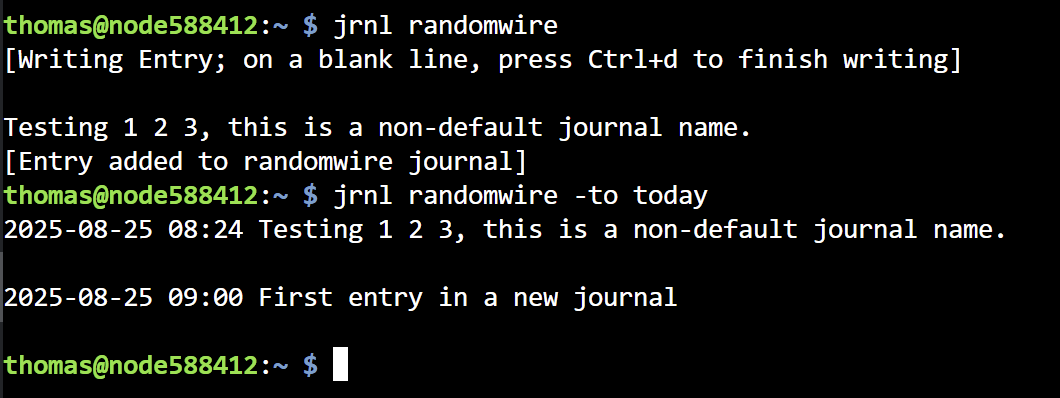
To make a note of something you are doing or just did, use jrnl today, as shown below. After making a couple of entries, I then used jrnl -to today to list the entries for the day.
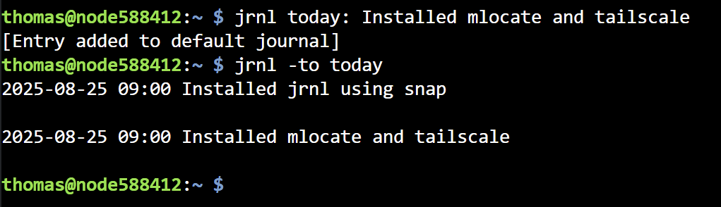
The jrnl basic usage page shows how to use jrnl. You can use tags in your jrnl entries and there are search and filter functions available to help you find specific information from your saved notes.
You can have multiple journals. As a test, I created a second journal named randomwire.txt. When you run the jrnl -to today command, you are telling jrnl to open the default journal. To access a non-default journal, you specify the journal name, e.g.: jrnl randomwire -to today. Specifying only the journal name prompts you to enter a note.
I know this style of keeping records is not going to appeal to many folks. I confess that it takes me back to a great time in my life when I was experimenting with managing a TO DO list with a batch file. (Yes, this was in the long ago!) Once that batch file was set up and running properly, this was a very simple way for me to keep track of things to do. This pre-dated my interest in GTD (Getting Things Done) and PIM (personal information manager) systems. jrnl hearkens back to those heady days of taming a computer to do useful things for me.
I can see myself dedicating a Raspberry Pi Zero just for running jrnl. Installed on a Debian 12 base and adding Tailscale, those records would be accessible to me from anywhere. A quick SSH session is all it would take to add, delete, or query my journals. Currently, I use Joplin (complicated when synchronizing journals), Notepad++ (reasonably simple but awkward), and LogSeq (slow, at least on every machine I’ve tried it on) to capture journal entries. Each of those solutions has something I don’t like. The “jrnl on one machine” approach is sounding more attractive the more I think about it!
Coming up
Vertical antenna — I have an old telescoping antenna package by MFJ that I pulled out of storage this week. I’m looking forward to getting that set up and seeing how it works.
EFHW antenna — I’ll probably also try to get an end-fed halfwave antenna up in the tree at the lake house. It’s quite tall. What worked last time I did this was a ball thrower (the kind you get to pick up and throw a slobbery ball for your dog) with a screw eye (secured with superglue) tied to some monofilament line. After several tries, I was able to get the rubber ball over a branch about 40 feet up. I’ve also tried a slingshot (which did work) but I kept breaking the slingshot bands. I’ve not yet tried an air launcher. Maybe it’s time for one.
Transceivers — I’ve pulled my Yaesu FT-450D and FT-891A radios out of storage. Over the next few weeks, I’m hoping to find some time to get one of them set up at the lake house. With an antenna up in the tree and the FT-450D running, I can pull a DigiRig device out of storage and do some digital radio work. I still need to find time to learn the HFSignals zBitx transceiver, too. Getting an EFHW antenna up will make that go quicker.
Raspberry Pi — I encountered an interesting case for a Raspberry Pi Zero: the Argon POD. The POD system are modular components that snap together to add ports or even add a 2.8-inch touch screen with four programmable buttons. I haven’t found anything already scripted for the screen that would work for an AllStar node, but the buttons could easily be programmed to safely shutdown and to reboot the node. I have a few POD pieces and will be experimenting with this system.
N9TAX Slim Jim antenna — The lake house is in an odd spot where some RF that comes in clearly just up the hill isn’t heard down by the lake. I bought an N9TAX Slim Jim 2M/70cm antenna and a crappie pole to see if hanging the antenna in free space would help. Answer: not yet.

Personal
This was a big week for us. My wife was discharged from the in-patient rehabilitation (IPR) facility in Tacoma, Washington. Our daughter and I transported her to the lake house on Wednesday, which happened to also be our 48th wedding anniversary. We’ll see how things go for the next few months. Physically, I don’t think the IPR helped her much, and frankly, that is disappointing. Emotionally, though, she seems much more settled…more herself. That indefinable spark that makes her who she has emerged more during her IPR stay. Example: several days ago, a nurse asked my wife if she had any pain. My wife got an impish grin on her face and pointed at me, then she and the nurse had a good laugh.
73 to all. Remember to touch a radio every day!


Leave a Reply